Theoretical Background
The Codelet Model is a hybrid von Neumann/Dataflow Program Execution Model (PXM) that differs from a sequential computer’s PXM in the following aspects:
Instead of a single program counter, there can be multiple program counters, allowing for concurrent execution of instructions from multiple parts of the program
Programs are divided into small sequences of instructions in a two-level hierarchy: Threaded Procedures (TP) and Codelets.
The order of execution among codelets is determined by data and control dependencies explicitly identified in the program, as opposed to the program order
Frames holding local context for functions are allocated from a heap rather than a linear stack
These features provide the operational semantics, with enough detail, so a programmer can accurately predict a given program’s behaviour at a given point in the program’s execution. It provides a basic set of primitive operations, which give specific details of instructions, registers as well as their interactions to support concurrent execution of Codelets.
Codelets
Based on Semi-Dynamic Dataflow principles, a Codelet is the combination of instructions, data dependencies and the definition of operational conditions. This definition allows for the reduction and the amortization of the synchronization overhead while also improving data locality. Codelets can be executed when all data dependencies have been met and there are enough computational resources available. The Codelet Model maintains the ordering constraints among instructions within one codelet, but loosens the constraints between different codelets. A Codelet is a sequential, non-preemptive, atomically-scheduled set of instructions. Representing a program as multiple sections of code allows the execution of instructions as soon as the data and resources are available.
Sequentially Executed: Modern processors perform sequential execution very efficiently, even when there are many dependencies among the instructions and can take advantage of the data locality which is usually present due to these dependencies. Leveraging instruction level parallelism (ILP) and the control mechanisms present in this kind of hardware provides desirable levels of performance without the need for additional, specialized hardware
Non-Preemptive: Once a Codelet begins execution, it remains active in the CPU until it is finished executing
Atomic Scheduling: A codelet cannot be interrupted, therefore it should not begin execution until it is guaranteed to finish without interference from other processes
Threaded Procedure (TP)
A TP consists of one or more Codelets. In the Codelet Model, a Codelet is always a part of an enclosing TP. All codelets in a procedure share the local variables and input parameters of that TP, much like context in modern programming languages. Objects may have a lifetime beyond a single procedure, may have a size which can’t be determined at the time the frame is allocated, or may be shared among multiple procedures. Some objects may even need to exist outside of a particular frame’s context. The tight coupling between codelets within these categories requires a fine-grain level of synchronization and data sharing mechanisms. The structure of an example threaded procedure is shown below.
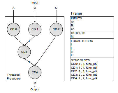
TPs and Codelets differ in their contexts, their lifetimes and their manner of invocation. The context of an instance of a TP is similar to the context of a function call in a conventional language such as C. Codelets have much smaller context, consisting only of registers and specialized state variables (SyncSlots). On the other hand, a TP instance remains “live” even if none of its Codelets are active or enabled; a TP must also explicitly terminate itself. TPs are invoked explicitly by the application program.
When the program invokes a TP, the machine creates a context for this procedure, initializing the input parameters with the values passed to this TP. A new frame is allocated in memory for this particular instance of the procedure. All codelets can access this frame through a unique frame identifier (FID), which is part of the invoking Codelet’s context and is normally kept in a register for quick access. This is similar to the frame pointer found in conventional block-structured languages. Given the FID, it is possible to access any local variable or input parameter within the corresponding TP’s instance context. This also allows the use of recursive calls. Because procedures are explicitly terminated, no garbage collection of frames is needed.
SyncSlots
A codelet needs to be sure that all dependencies have been satisfied before it is enabled, since the Codelet can’t be preempted once started. A counter is used to count the incoming signals so it is known when a Codelet is ready to be enabled. The Codelet model allows for the instantiation of SyncSlots to control different Codelets simultaneously along with allowing several counters to control the same Codelet.
A SyncSlot contains:
SyncCount (SC): Indicates the number of dependencies to be received by the SyncSlot before the specified Codelet can be enabled.
ResetCount (RC): If the SyncCount reaches 0 the Codelet specified by the SyncPointer is enabled. After the Codelet execution starts, the SC is set back to the RC.
SyncPointer (SP): Binds the SyncSlot to one of the Codelets in the TP.
The SyncSlot counts the number of tokens received. Sending a SyncSignal is sufficient if and only if both sender and receiver are in the same TP instance. This is because local variables can be used to transfer the data from one Codelet to another. Because the SyncSlots are used for controlling the enabling of Codelets, they must persist beyond the lifetime of a Codelet, and therefore must be part of the context of a TP. The use of a RC allows Codelets to be enabled multiple times.
Each Codelet is part of an enclosing TP, a given instance of a Codelet is associated with one particular procedure instance. Each Codelet is given a unique Codelet identifier (CID). Each instance of a codelet can be uniquely identified by a pair (FID, CID).
Codelet Abstract Machine
What this model has in common with other parallel paradigms is the division of a program into multiple sections of code, defined as Codelets. Combining individual instructions into Codelets reduces and amortizes the overheads of synchronization and improve data locality. A Codelet that is not ready to begin execution is classified as dormant. When the system decides a codelet is ready to execute, it enables the Codelet. Since the CPU may still be busy with other codelets at that time, there may be a delay between the time a codelet is enabled and the time it starts running. We refer to the first state as enabled while the latter state is considered active.
The picture below shows an abstract model of a machine for executing Codelets. There are two pools of Codelets: one for dormant Codelets and the other one for enabled codelets. When Codelets are enabled, they are moved from the dormant pool to the enabled pool. When the Active Codelet Processor has available resources for executing the Codelet, it takes one from the enabled pool, making it active. At the same time, it must allocate the required resources needed by this Codelet and begins execution.
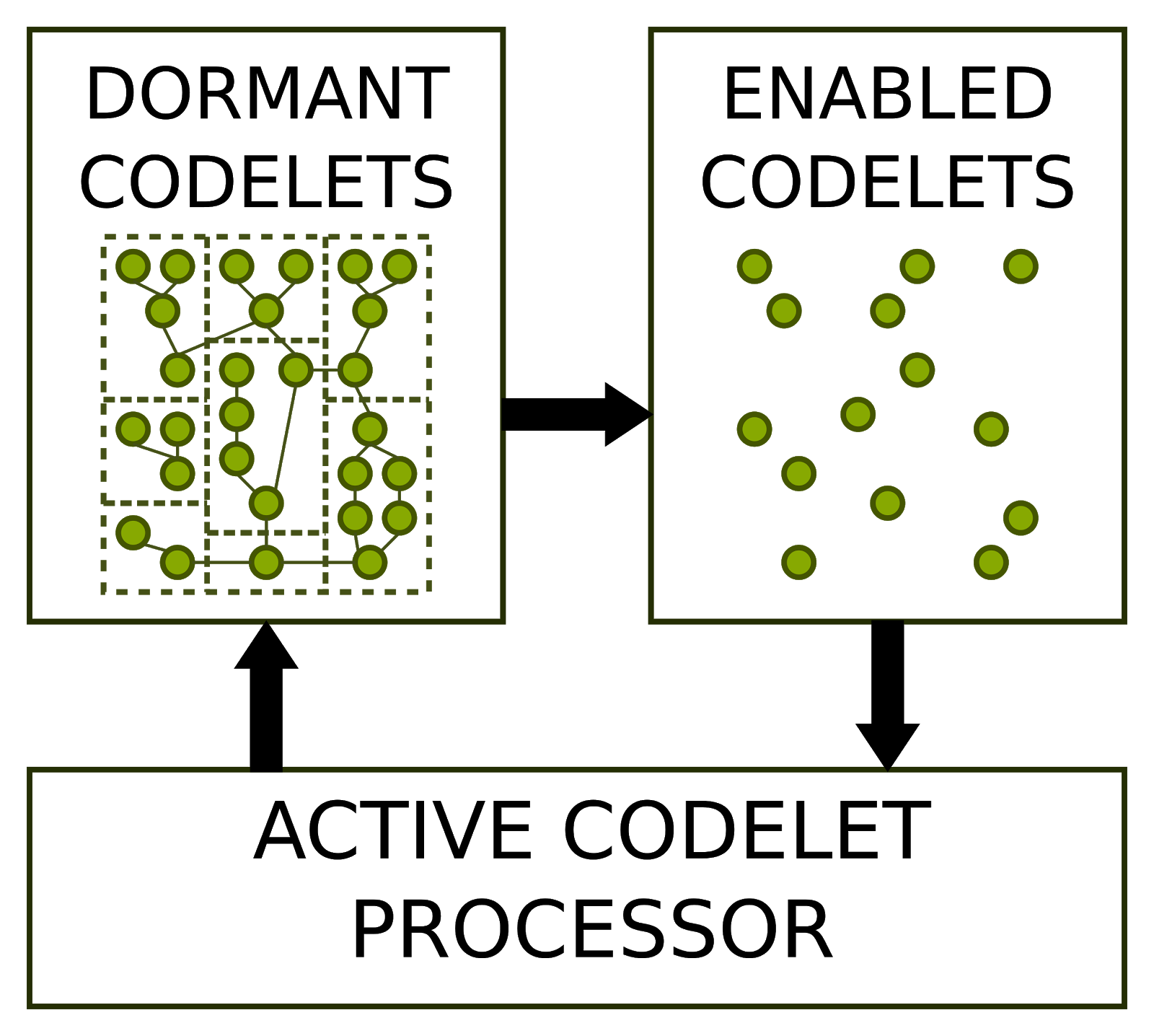
A two-layer hierarchy of Codelets and TPs adds flexibility, programmability and support for current off-the-shelf processors. When a procedure is invoked, the system must first allocate and initialize the frame. Once this stage is completed, the initial Codelet is enabled, and begins waiting for the machine to have sufficient resources available for execution. All other Codelets in the procedure must rely on other mechanisms to become enabled.
The machine must check and verify dynamically that all data and control dependencies have been satisfied before enabling a Codelet. Using Synchronization Signals (SyncSig) and Synchronization Slots (SyncSlots). A synchronization signal, or SyncSig, is sent from one Codelet to another, either in the same or another procedural instance, to alert the recipient that a specific control or data dependency has been satisfied.
Memory Model
Most large multiprocessors use either distributed memory or distributed shared memory. Distributed memory architectures have separate memories for each processor or group of processors. These are separate both physically and logically. A process can access data in remote memory only indirectly, by communicating with a process that has access to that memory (often referred as message passing machines). Distributed shared memory architectures have a global address space, which allows any processor to access any memory location in the system. The Codelet PXM is neither restricted to distributed memory machines nor limited by them.
To support the Codelet PXM, a machine’s memory system must have the following properties: An active Codelet must have direct, low-latency access (through load and store operations) both to its private Codelet context and to the frame it shares with other Codelets in the same procedural instance An active sequential function call must have direct, low-latency access both to its local linear stack and to the frame belonging to the Codelet which initiated the sequential function call (either directly or through other function calls) Instruction pointers are uniform through the system. The code for all threaded procedures and sequential functions is accessible from all processing elements of the machine, and given SP value has the same meaning on all such elements. The instruction addresses used in sequential function calls must be the same on all processing elements
All objects in the system which may be accessible by more than one TP. This includes FID, SyncSlots or any data addresses which may be bound with SyncSignals; though they must be globally unique and accessible by special Codelet Model operations.
Since all Codelets within a TP share data in a single frame, all Codelets in a given TP must run on a processor or processors with access to the same context. The first three requirements ensure rapid execution within a Codelet and guarantees that procedures and sequential functions can be invoked on any processing element. This allows for Codelets to communicate seamlessly with other procedures. Each processor must be able to determine the exact location of any given memory reference.
Communication Mechanisms
Each element (TP, Codelet, SyncSlot) and each instance of those in the PXM is referenced by a unique identifier. Memory references, at least those passed between procedures, must be globally unique across the machine, and each processor must be able to determine the exact location of any given memory reference. The Codelet Model Defines atomic operations for sending data and a SyncSignal together. This Data-Transfer/SyncSignal operation may be initiated by the producer of the data, which sends local data to another location, or by the consumer, which sends a request for remote data to the system. The latter operation is called a split-phase transaction because the request and data transfer may occur in distinct phases.
Operations
The execution of a Codelet-based program relies on various operations for sequencing and manipulating the Codelets in this PXM. These operations perform the following functions: Invocation and termination of TPs and Codelets Creation and manipulation of SyncSlots Sending of SyncSignals to SyncSlots, either alone or atomically bound with data.
The Embedded System
The Parallella board used is an affordable, highly parallel and open source embedded system. The board features a programmable logic/main processor combined chip (z7010/z7020), a multi-core accelerator (Epiphany), and some peripherals. The accelerator operates on a RISC architecture and is used to offload computation for acceleration. It is the accelerator, together with its low cost and the openness of its software stack, that makes the embedded system unique and a great fit for our purpose. The board runs full-fledged Ubuntu 15.04, modified to contain the drivers that communicate with the accelerator through some programmable logic running on the FPGA.
Each of the cores of the accelerator has 32 KB of scratchpad memory that can be accessed by other cores. There is no coherency protocol, the memory model is relaxed and there are a couple of instructions that allow atomic access. The user is responsible for managing this memory and use it for code and data. For programming the system it is possible to use C, some limited functionalities of C++, and assembly. However, all of the software stack (i.e. operating system, drivers, libraries, and FPGA code) is fully open source.
Thanks to these properties, the system is highly flexible and customizable, while its barebones design allows us to remove some of the burden present in current microprocessors (e.g. cache coherency protocols) that have shown to be detrimental to the performance of the Codelet Model implementations. However, it also makes the realization of this project more challenging.
MPI
A standard Message Passing Interface for distributed memory concurrent computers and networks of workstations. Provides the communication and synchronization mechanisms to share control and data among the different nodes through the network. The main advantages of using MPI are the portability, ease-of-use and a clearly defined set of routines.
OpenMP
Open Multi-Processing, is an application programming interface (API) that supports multi-platform shared memory multiprocessing programming in C, C++ and Fortran. It consists of a set of compiler directives, library routines and environment variables that influence run-time behavior. It is used for communication and synchronization between the main processor cores in a single node.
Protocol Buffers
Protocol buffers (or protobuffers) offer the programmer an intuitive interface to serialize structured data across different languages and platforms in an intuitive, extensible fashion. The programmer will input how they wish for their messages to be formatted, much like XML. Google Protobuffers highlight they are “smaller, faster and simpler” than their XML equivalents. In comparison to XML formatting, protocol buffers offer a solution that can be 3-10x smaller, resulting in a performance improvement of 20-100x times when parsing or de-serializing. Additionally, the syntax of protocol buffers is less ambiguous than its counterpart XML files.
A second advantage of Protocol Buffers is that it is meant to create interfaces that natively map into different programming languages. Therefore, the same protobuffer description file can be used to generate native libraries in C, C++, Java, Go language and others. Therefore improving programmability, usability and performance. All of this configuration is carried out in the .proto file for the project. Within this one file, multiple languages are easily and comprehensively generate applicable source code.
How to Use Protobuffer Files for Neural Networks
Protocol buffers are a general method to describe any sort of information. The programmer must first specify how they want their data interpreted in terms of messages. However, Google has used protocol buffers for their Tensorflow runtime in order to describe neural networks that are to be executed in the underlying Tensorflow runtime. The magic resides in that protocol buffers support C/C++/Objective-C, Python, Go, Ruby and C#. Therefore, it is possible to create front ends in these programming languages that will generate neural networks represented using the graph definitions that can be interpreted by the runtime located in the back end. In the meantime, the back end will implement each of the operations needed for the execution of the neural networks.
Tensorflow’s neural networks definitions include the concept of Graph as a collection of nodes. Each node has at least: a list of predecessor nodes, an operation type, and a set of attributes containing additional information of the network. It is possible to store untrained neural networks that contain no particular weights or values representing just the structure of the network. Additionally, it is possible to store so-called “frozen” neural networks that are fully trained model ready to be used for execution.
Facial Landmark Detection Algorithm
Face detection is a problem in computer vision for locating and localizing one or more faces in a photograph. Locating a face in a photograph refers to finding the coordinates of the face in the image, whereas localization refers to demarcating the extent of the face, often via a bounding box around the face. Detecting faces in a photograph is easily solved by humans, although has historically been challenging for computers given the dynamic nature of faces.
For facial landmark detection, we have selected the Multi-task Convolutional Neural Network (MTCNN) algorithm developed by Kaipeng Zhang et al. We chose this algorithm as the neural network is large enough and fast enough exploit advantages of the dataflow based execution model. The MTCNN model consists of 3 separate networks: the P-Net, the R-Net, and the O-Net.
In the P-Net, for each scaled image, a 12x12 kernel runs through the image, searching for a face. Within each of these 12x12 kernels, 3 convolutions are run through with 3x3 kernels. After every convolution layer, a prelu layer is implemented. In addition, a maxpool layer is put in after the first prelu layer. After the third convolution layer, the network splits into two layers. The activations from the third layer are passed to two separate convolution layers, and a softmax layer after one of those convolution layers. One of the convolution layers outputs the probability of a face being in each bounding box, while the other convolution outputs the coordinates of the bounding boxes.
R-Net has a similar structure, but with even more layers. It takes the P-Net bounding boxes as its inputs, and refines its coordinates. he end, giving out two outputs: the coordinates of the new bounding boxes and the machine’s confidence in each bounding box. Finally, O-Net takes the R-Net bounding boxes as inputs and marks down the coordinates of facial landmarks.
Dataflow inspired Neural Network chips
Deep learning has emerged as one of the most important computational workloads in recent years. To meet its growing computations demands, we have seen a rise in the development of dataflow inspired chips specialized for processing neural networks.
Cerebras is one of the projects where its cores are designed specifically for the sparse linear algebra of neural networks. To take advantage of this sparsity, the core has built-in, fine-grained dataflow scheduling, so that the compute is triggered by the data. We should also note the importance of software stack and Program Execution Model (PXM) highlighted by this project. The Cerebras software stack provides a seamless interface to existing high-level ML frameworks, such as TensorFlow and PyTorch. The graph compiler begins by extracting a dataflow graph representation of the neural network from the user-provided framework representation.
The Tianjic chip adopts a many-core architecture, reconfigurable building blocks and a streamlined dataflow with hybrid coding schemes, and can not only accommodate computer-science-based machine-learning algorithms, but also easily implement brain-inspired circuits and several coding schemes. By forming a parallel on-chip memory hierarchy and organizing the dataflow in a streaming fashion, the Tianjic chip can provide improved throughput and power efficiency.